fredag 29. oktober 2010

Continuing serial mouse experimentation

So I've been around the web, found many useful resources for how to incorporate my serial mouse to a project. A very special example is the Serial Mouse -> Etch a Sketch project. There, among many other places, I learned the UART protocol for my device is "Microsoft Mouse"-protocol, a standard protocol for serial interface computer mice.

The Microsoft Mouse protocol consists of 3 bytes sent individually as a package of 7 bits per byte (which is not a full byte) in a specific order each time an event occurs on one the mouse's motion detectors (movement, button press or button release).
Byte 1 |  1   LB  RB  Y7  Y6  X7  X6
Byte 2 |  0   X5  X4  X3  X2  X1  X0
Byte 3 |  0   Y5  Y4  Y3  Y2  Y1  Y0
  • MSB at Byte 1 is always set to indicate the start of a package.
  • LB and RB represents Left and Right button, active high.
  • Y0-Y7 represents movement in Y position in 8 bit 2's compliment
  • X0-X7 represents movement in X position in 8 bit 2's compliment
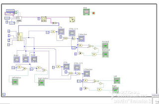
I wanted to test this and started setting it up in LabVIEW using the VISA serial driver. As always, LabVIEW looks like crap when it's all set up in the block diagram, with little or no possibilities for comments.
   To get the full 8 bit value of Y-position i logically AND'ed byte 1 with the binary representation of the Y7 and Y6 bit, then bit-shifted it 4 times to the left, and OR'ed it with the rest of the Y values in Byte 3.
so
((Byte 1 & 12)<<4) | Byte 3 = Y position, likewise
((Byte 1 & 3)<<6) | Byte 2 = X position 
if (Byte 1  & 32) == 32 {Left button press}

if (Byte 1 & 16) == 16 {Right button press} 
To check which direction the mouse is moving, I could check if the signed (MSB) bit is high (negative value) or low (positive value). All though, it could be that the signed bit is low when the whole direction "register" is 0, so you would have to test both conditions to get both directions and eliminate the states when there is no movement at all.

Here is the finished front panel

And here is the messy block diagram

And here is a video, hopefully the "LEDs" and animation will be less choppy on a faster computer

søndag 24. oktober 2010

Logitech M-M28 serial interface computer mouse

This article is continued here

Sometimes, looking around the electronics trash at my local electronics dealer could feel like a walk in the candy store (where candy is free). Todays find is the Logitech M-M28 serial computer mouse, and boy was I happy when I got back home to google this thing. They go for over $50 on some webshops!
So little information, only logitech them self is the only source of info, though they only provide the line "First Mouse™ M-M28 SerialM" Where SerialM is the "DeviceModel =string" (?). This is the detection string the driver uses to draw the correct picture of the device in the Mouse Properties. This information is stored in the Windows Registry. 
But where is the driver? Doesn't really matter, does it? As you have already thought, I will not replace my USB optical mouse with this, I wan't to use this in a project somehow. I'd appreciate a comment if you have a good idea of implementing this thing in some way.

 The thing is in mint condition, glad I found it before the snow came falling down.

I connected it to the stationary computer at my home laboratory, and sure enough it outputs some specific bytes on each 1/20 turn or so on the rotary encoders and on mouse clicks. But when I got to my apartment using my Win 7 laptop with a USB-serial converter and Putty instead of HyperTerminal I don't get any output. Hopefully I can capture some screenshots at one of the stationary computers at school tomorrow.

Here is a look inside
I have not found any information on the chip manufactured by Motorola(?) for Logitech. In case you don't want to read it all from the picture, here is what is says
LOGITECH 92
330070-00MI
E31AQLMT9417
Pretty simple construction, with the chip doing all the work on both decoding the rotary encoders and RS232 signal transmitting.

Servo signal to PWM motor controller on home made chassis. Atmega8 & L293D

A project that has been sitting with me for a while. I have tried some pre-made motorcontrollers on other projects, but none of them seemed to work the way I wanted (ESCs are not widely available for brushed DC motors). This home made motor controller is not perfect, no where near, but the fun part was learning along the way.

The motor controller consists of a "FlySky" 6 channel RC receiver which outputs 1-2ms wide servo pulses of 5 volts amplitude. Two of these signals are converted by the Atmega8 microcontroller to provide 0-100% PWM for the L293D chip to amplify. The controller can also reverse the motors, so the PWM is actually at 100% duty cycle at both endpoints of the RC throttle stick (1ms and 2ms pulses from Rx on board) and 0% duty cycle when throttle is in center position (1.5ms from Rx). 2 digital output pins from the Atmega8 tells the L293D chip which way the motor will spin.

When recording the video I was out of 9 volt batteries, so had to use external supply. That is why the car can just drive at my desk at the moment :)

This is the first sketch for the motor controller circuit. Later I have added caps to the 7805 voltage regulator, and decided I wanted a separate battery for the logic and the motor supply.

Here is a short movie of my car