I decided to move my whole blog to WordPress which I am hosting on a rented web server. Luckily, the import from blogger to WordPress was painless, and it only took a couple of minutes to set up!
Visit me at my new address
Henrik.SandakerPalm.no
tirsdag 7. desember 2010
tirsdag 2. november 2010
My first repair job, LG LCD TV didn't turn fully on.
Gladly, I was able to fix this TV with some hints I have gotten from somewhere I don't remember. When the owner presented me with the fault (it would sometimes not turn fully on, most of the time not at all) I knew it would probably be some big filter capacitors on the power supply. I think I've read this on the all about circuits forum. So I got the TV and opened up the back cover.

Then goes the protection cover for the main board and power supply unit.
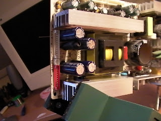
 The power supply is the PCB on the left, with the big heatsinks and capacitors. It is always a good thing to photograph a job like this before you disconnect everything, so you can more easier reassemble it. On the top near one of the output pins I found four bulging capacitors, 2 x 1000uF 25V and 2 x 1000uF 35V. I replaced all four with 1000uF 35V, as the 50V ones I could buy would not fit inside the power supply housing (you should always consider increasing the voltage tolerance when replacing blown capacitors).
The TV was as good as new!

Then goes the protection cover for the main board and power supply unit.

 |
| The old ones, bulging at the top. |
 |
| The four new ones. |
 | |||
| With lots of flux the old solder didn't make to much mess when re-soldering. |
fredag 29. oktober 2010
Continuing serial mouse experimentation
So I've been around the web, found many useful resources for how to incorporate my serial mouse to a project. A very special example is the Serial Mouse -> Etch a Sketch project. There, among many other places, I learned the UART protocol for my device is "Microsoft Mouse"-protocol, a standard protocol for serial interface computer mice.
The Microsoft Mouse protocol consists of 3 bytes sent individually as a package of 7 bits per byte (which is not a full byte) in a specific order each time an event occurs on one the mouse's motion detectors (movement, button press or button release).
To get the full 8 bit value of Y-position i logically AND'ed byte 1 with the binary representation of the Y7 and Y6 bit, then bit-shifted it 4 times to the left, and OR'ed it with the rest of the Y values in Byte 3.
so
Here is the finished front panel

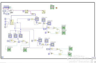
And here is the messy block diagram
And here is a video, hopefully the "LEDs" and animation will be less choppy on a faster computer
The Microsoft Mouse protocol consists of 3 bytes sent individually as a package of 7 bits per byte (which is not a full byte) in a specific order each time an event occurs on one the mouse's motion detectors (movement, button press or button release).
Byte 1 | 1 LB RB Y7 Y6 X7 X6
Byte 2 | 0 X5 X4 X3 X2 X1 X0
Byte 3 | 0 Y5 Y4 Y3 Y2 Y1 Y0
- MSB at Byte 1 is always set to indicate the start of a package.
- LB and RB represents Left and Right button, active high.
- Y0-Y7 represents movement in Y position in 8 bit 2's compliment
- X0-X7 represents movement in X position in 8 bit 2's compliment
To get the full 8 bit value of Y-position i logically AND'ed byte 1 with the binary representation of the Y7 and Y6 bit, then bit-shifted it 4 times to the left, and OR'ed it with the rest of the Y values in Byte 3.
so
((Byte 1 & 12)<<4) | Byte 3 = Y position, likewise
((Byte 1 & 3)<<6) | Byte 2 = X position
if (Byte 1 & 32) == 32 {Left button press}To check which direction the mouse is moving, I could check if the signed (MSB) bit is high (negative value) or low (positive value). All though, it could be that the signed bit is low when the whole direction "register" is 0, so you would have to test both conditions to get both directions and eliminate the states when there is no movement at all.
if (Byte 1 & 16) == 16 {Right button press}
Here is the finished front panel

And here is the messy block diagram

And here is a video, hopefully the "LEDs" and animation will be less choppy on a faster computer
søndag 24. oktober 2010
Logitech M-M28 serial interface computer mouse
This article is continued here
Sometimes, looking around the electronics trash at my local electronics dealer could feel like a walk in the candy store (where candy is free). Todays find is the Logitech M-M28 serial computer mouse, and boy was I happy when I got back home to google this thing. They go for over $50 on some webshops!
So little information, only logitech them self is the only source of info, though they only provide the line "First Mouse™ M-M28 SerialM" Where SerialM is the "DeviceModel =string" (?). This is the detection string the driver uses to draw the correct picture of the device in the Mouse Properties. This information is stored in the Windows Registry.
But where is the driver? Doesn't really matter, does it? As you have already thought, I will not replace my USB optical mouse with this, I wan't to use this in a project somehow. I'd appreciate a comment if you have a good idea of implementing this thing in some way.
 The thing is in mint condition, glad I found it before the snow came falling down.
I connected it to the stationary computer at my home laboratory, and sure enough it outputs some specific bytes on each 1/20 turn or so on the rotary encoders and on mouse clicks. But when I got to my apartment using my Win 7 laptop with a USB-serial converter and Putty instead of HyperTerminal I don't get any output. Hopefully I can capture some screenshots at one of the stationary computers at school tomorrow.
Here is a look inside
 I have not found any information on the chip manufactured by Motorola(?) for Logitech. In case you don't want to read it all from the picture, here is what is says
LOGITECH 92
330070-00MI
E31AQLMT9417
Pretty simple construction, with the chip doing all the work on both decoding the rotary encoders and RS232 signal transmitting.
Sometimes, looking around the electronics trash at my local electronics dealer could feel like a walk in the candy store (where candy is free). Todays find is the Logitech M-M28 serial computer mouse, and boy was I happy when I got back home to google this thing. They go for over $50 on some webshops!
So little information, only logitech them self is the only source of info, though they only provide the line "First Mouse™ M-M28 SerialM" Where SerialM is the "DeviceModel =string" (?). This is the detection string the driver uses to draw the correct picture of the device in the Mouse Properties. This information is stored in the Windows Registry.
But where is the driver? Doesn't really matter, does it? As you have already thought, I will not replace my USB optical mouse with this, I wan't to use this in a project somehow. I'd appreciate a comment if you have a good idea of implementing this thing in some way.

I connected it to the stationary computer at my home laboratory, and sure enough it outputs some specific bytes on each 1/20 turn or so on the rotary encoders and on mouse clicks. But when I got to my apartment using my Win 7 laptop with a USB-serial converter and Putty instead of HyperTerminal I don't get any output. Hopefully I can capture some screenshots at one of the stationary computers at school tomorrow.
Here is a look inside

LOGITECH 92
330070-00MI
E31AQLMT9417
Pretty simple construction, with the chip doing all the work on both decoding the rotary encoders and RS232 signal transmitting.
Servo signal to PWM motor controller on home made chassis. Atmega8 & L293D
A project that has been sitting with me for a while. I have tried some pre-made motorcontrollers on other projects, but none of them seemed to work the way I wanted (ESCs are not widely available for brushed DC motors). This home made motor controller is not perfect, no where near, but the fun part was learning along the way.
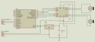
The motor controller consists of a "FlySky" 6 channel RC receiver which outputs 1-2ms wide servo pulses of 5 volts amplitude. Two of these signals are converted by the Atmega8 microcontroller to provide 0-100% PWM for the L293D chip to amplify. The controller can also reverse the motors, so the PWM is actually at 100% duty cycle at both endpoints of the RC throttle stick (1ms and 2ms pulses from Rx on board) and 0% duty cycle when throttle is in center position (1.5ms from Rx). 2 digital output pins from the Atmega8 tells the L293D chip which way the motor will spin.
When recording the video I was out of 9 volt batteries, so had to use external supply. That is why the car can just drive at my desk at the moment :)
This is the first sketch for the motor controller circuit. Later I have added caps to the 7805 voltage regulator, and decided I wanted a separate battery for the logic and the motor supply.
Here is a short movie of my car
The motor controller consists of a "FlySky" 6 channel RC receiver which outputs 1-2ms wide servo pulses of 5 volts amplitude. Two of these signals are converted by the Atmega8 microcontroller to provide 0-100% PWM for the L293D chip to amplify. The controller can also reverse the motors, so the PWM is actually at 100% duty cycle at both endpoints of the RC throttle stick (1ms and 2ms pulses from Rx on board) and 0% duty cycle when throttle is in center position (1.5ms from Rx). 2 digital output pins from the Atmega8 tells the L293D chip which way the motor will spin.
When recording the video I was out of 9 volt batteries, so had to use external supply. That is why the car can just drive at my desk at the moment :)
This is the first sketch for the motor controller circuit. Later I have added caps to the 7805 voltage regulator, and decided I wanted a separate battery for the logic and the motor supply.

Here is a short movie of my car
søndag 19. september 2010
DYP-ME007 with an AtMega8 AVR microcontroller

I wanted to be able to read the distance captured from the ultrasonic range finder device on a microcontroller, to know how to implement this device in a possibly bigger and more complex circuit later on. Starting simple, this code prints out a pattern relative to the distance output of the DYP-ME007. I am using my Atmel STK500 for both programming and operation of the AtMega8, and the pattern will be displayed on the STK500 leds. The comments in the C code will describe what is being done and why. Since C code specific syntax highlighting is not one of blogspots features, I will add a clean syntax highlighted image, and you can always download the code here.
The video quality is no good, but it's easy to see what is going on. Notice the waveform on the scope in the background.
fredag 17. september 2010
Testbench for DYP-ME007 Ultrasonic Range Finder
This is how I set up the test bench for configuring and also just figuring out the DYP-ME007 Ultrasonic Range Finder, bought at GoodLuckBuy.com.
http://www.goodluckbuy.com/ultrasonic-wave-detector-ranging-module-distance-sensor.html
The usage is the same as for the popular SRF0004 equivalent;
The Vcc should be connected to 5v, Gnd is ground. When you pulse the trigger pin at TTL HIGH level (for at least 10uS) the echo pin will go TTL (5v) HIGH for a period proportional to the length between the DYP-ME007 and the nearest object. The period length is actually the time it takes for a ultrasonic sound to travel forth and back to the DYP-ME007 module. Don't mind the other components to the left and right for the module on the picture!
I suspected there would be some problems with contact bounce at the switch, but fortunately I did not have to deal with that.
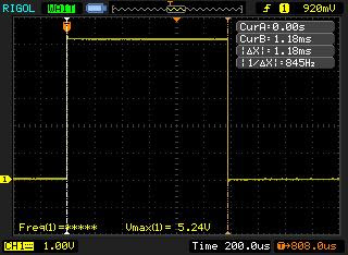
These are the readings I got from the oscilloscope. The scope was set up to trigger on a positive edged pulse of amplitude 1v or higher, which is within safe limits for the 5v pulse.
As you can see from the scope screen captures, the pulse width is very much proportional with length it measures. When I double the length, the pulse doubles the width. From the cursor readings you can easily see that the pulse width is approx. 600uS for each 10 centimeters.
http://www.goodluckbuy.com/ultrasonic-wave-detector-ranging-module-distance-sensor.html
The usage is the same as for the popular SRF0004 equivalent;
The Vcc should be connected to 5v, Gnd is ground. When you pulse the trigger pin at TTL HIGH level (for at least 10uS) the echo pin will go TTL (5v) HIGH for a period proportional to the length between the DYP-ME007 and the nearest object. The period length is actually the time it takes for a ultrasonic sound to travel forth and back to the DYP-ME007 module. Don't mind the other components to the left and right for the module on the picture!
 |
| This is how I physically set up the test bench |
 |
| This is the wiring scheme for the simple test bench |
I suspected there would be some problems with contact bounce at the switch, but fortunately I did not have to deal with that.
These are the readings I got from the oscilloscope. The scope was set up to trigger on a positive edged pulse of amplitude 1v or higher, which is within safe limits for the 5v pulse.
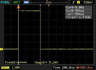 |
| Scope readings on 10cm distance |
 |
| Scope readings on 20cm distance |
First blog entry, lab showoff

From the right, there is the MASTECH MS8040 benchtop multimeter.
I love the big back-lit display, the intuitive operation and that it has all functions and need plus many more.
Bought on ebay. This product is no longer produced, so I have no link to the manufacturers specific product site, but you can still find it on ebay, and its cheap.
Next is my main power supply from Maplin store, England. 20 volts, 5 Amps max. Mode for both constant current and constant voltage and a big back-lit display. When testing big application with big motors and such I use separate power supplies salvaged from printers and other hardware.
http://www.maplin.co.uk/Module.aspx?ModuleNo=219129
Besides my main power supply is my smaller "backup" power supply. It has only 6 voltage settings, 3, 4.5, 6, 7.5, 9 and 12 volts. 1.5 amps maximum. I mostly use this to power my RC transmitter while experimenting so I don't have to use up all my batteries on this.
http://www.biltema.no/no/Kontor---Teknikk/Batteri-og-Stromforsyning/Nettaggregat-og-ladere/Nettaggregat-312-V/
Then comes my soldering station. Regulated, 150-450 degrees Celsius. This station is not as temperature stable as I would like it, but is OK for most applications. Also not beeing produced anymore, but has been replaced by a similar one with digital HMI.
http://www.biltema.no/no/Verktoy/Sveising-og-lodding/Loddeverktoy/Loddestasjon/
My newest addition to my lab instrument collection is the 50 MHz Rigol DS1052E oscilloscope. See http://www.eevblog.com/2009/04/05/full-review-of-the-rigol-ds1052e/ for a full review of this. I have to say this is one of the best money I have ever spent! After using the oscilloscopes at school, I quickly found out I wanted one at home. My teacher said I had to spend around $1000 for a decent scope. Needless to say, I was disappointed. Luckily, I found this on one of my favorite webshops, dealextreme.com, read the review and purchased it. DX never sent me the item, so 3-4 months later I ordered it from goodluckbuy.com, which is now my first choice for cheap gadgets and other hardware.
http://www.goodluckbuy.com/rigol-oscilloscope.html
The green PCB with jumper wires is the Atmel STK500 evaluation board for the AVR series microcontrollers. I really could not do anything without this.
http://www.atmel.com/dyn/products/tools_card.asp?tool_id=2735
Abonner på:
Innlegg (Atom)